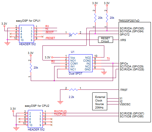
First step, SCI booting done by GPIO85/GPIO84 and later monitoring done by the other GPIOs. To do so, additional hardware is necessary to switch easyDSP connection from GPIO85/GPIO84 to the other GPIOs right after booting completion. Please refer to below circuit whereDual SPDT (NLAS4684 from Onsemi,TS3A24159 from TI ) is used. FPGA can be used too.
http://www.onsemi.com/pub_link/Collateral/NLAS4684-D.PDF
http://www.ti.com/lit/ds/symlink/ts3a24159.pdf

To switch easyDSP connection, one more GPIO (here, GPIOx) is used. You can use any GPIO which you don't use in your application. The operation mechanism as below.
- After reset, GPIOx is input pin as reset default. The pull-up resistor on GPIOx decides SPDT connection, which makes easyDSP connected to GPIO85/84.- Once SCI booting is completed, it's user's task to switch easyDSP connection to the other ports. You can do as below.
- Makes GPIOx as output port and set its value to low, which makes easyDSP connection to GPIO28/29.
- The above operation can be done ineasyDSP_SCI_Init() in CPU1.
- Please change original coding as recommended below.
///////////////////////////////////////////////////////////////////////////////////
// ORIGINAL CODING : SCI-A GPIO setting : SCIRXDA = GPIO 85, SCITXDA =
GPIO84
///////////////////////////////////////////////////////////////////////////////////
GPIO_SetupPinMux(84, GPIO_MUX_CPU1, 5);
GPIO_SetupPinMux(85, GPIO_MUX_CPU1, 5);
GPIO_SetupPinOptions(84, GPIO_OUTPUT, GPIO_ASYNC);
GPIO_SetupPinOptions(85, GPIO_INPUT, GPIO_ASYNC);
EALLOW;
GpioCtrlRegs.GPCPUD.bit.GPIO85 = 0;
GpioCtrlRegs.GPCPUD.bit.GPIO84 = 0;
EDIS;
//////////////////////////////////////////////////////////////////////////////////
// MODIFIED CODING : SCI-A GPIO setting : SCIRXDA = GPIO 28, SCITXDA =
GPIO29
//////////////////////////////////////////////////////////////////////////////////
GPIO_SetupPinMux(29, GPIO_MUX_CPU1, 1);
GPIO_SetupPinMux(28, GPIO_MUX_CPU1, 1);
GPIO_SetupPinOptions(29, GPIO_OUTPUT, GPIO_ASYNC);
GPIO_SetupPinOptions(28, GPIO_INPUT, GPIO_ASYNC);
EALLOW;
GpioCtrlRegs.GPCPUD.bit.GPIO28 = 0;
GpioCtrlRegs.GPCPUD.bit.GPIO29 = 0;
EDIS;
// easyDSP connected to GPIO28/29 by using GPIO31
GPIO_SetupPinMux(31, GPIO_MUX_CPU1, 0);
GPIO_SetupPinOptions(31, GPIO_OUTPUT, GPIO_PUSHPULL);
GPIO_WritePin(31, 0);
/BOOT pin of easyDSP pod has pseudo open
collector type, which means it becomes low during booting for flash
programming or RAM booting but open after booting. So, no addtional measures
are required when using GPIO72 as EMIF. But please note that easyDSP pod
connection or disconnection during MCU operation is not recommended since
it could make a unintended noise signal to GPIO72. 